Tuesday, April 30, 2013
Owners Manual 2012 Dodge Durango
 |
| Google Images |
Friday, April 26, 2013
2013 Ford Mustang Owners Manual Pdf
 |
| Google Images |
Friday, April 12, 2013
2002 Honda Civic Sd Owners manual
Congratulations Your assortment of a 2002 Honda Civic used to be once a smart funding. It will present you twelve monthss of using pleasure.As you examine this information, you\'ll to search out knowledge that\'s preceded via using the utilization of an emblem. This info is supposed that may make it extra simple to stay away from damage to your Honda, completely completely different property, or the ambiance.
Download: 2002 honda Civic Sd Owners guide
Thursday, April 11, 2013
Get Original 2013 Mazda 3 Owners Manual
 |
| Image By auto123.com |
There isnt a set information dealing with expenses for the 2013 Mazda 3. So, this material cannot discuss about it even though everyone is actually considering details. It is possible to see some other material to complete details you get from this material. There are many material discuss about the topic. You can select one then research it to get the cost.
That is all specifics about the new 2013 Mazda 3 sedan design. Hopefully, this material is actually able to help you choose whether you will buy the car or not. If you feel this material isnt addressing your problem about the 2013 Mazda 3, youll discover the reaction by learning other sources. Download Get Original 2013 Mazda 3 Owners Manual PDF Free.
Wednesday, April 10, 2013
1998 Toyota Camry CE Sedan L4 2164cc DOHC de 2 2 litros MFI reparación manual
.MIL ON - DTC P1133 Actualizado (Circuito del sensor de oxígeno). Notas ^ 1997 - 1999 el año del modelo Camry con 5S-FE California especificaciones de emisión. ^ 1999 Solaras modelo del año con 5S-FE California especificaciones de emisión ...
Descarga: 1998 Toyota Camry Sedan CE L4-2164cc DOHC de 2,2 litros MFI reparación manual
know about the dangers of a car ac
Benzene is a toxin who attack the liver, kidneys, lungs, heart and brain and can cause damage kromosonal. currently being conducted research on the effect of benzene on the level of fertility of men and women.Benzene is a poison the cat because our bodies are difficult to remove these toxins.Benzene is received in the room rate is 50 mg per square meter. A car parked indoors with windows closed will contain 400-800 mg of Benzene.
If parked outdoors under the sun at temperatures above 60 degrees Fahrenheit, the level of Benzene increased to 2000-4000 mg, are actually up 40 times more.People in cars would be inhaled some toxic excess.
So from that, before the car ignited the car and Conditioning, the better your car window open all the time and give the cars interior to breathe fresh air.
Tuesday, April 9, 2013
How does gear ratio affect Torque
Torque is a twisting force- (it doesnt do any work itself- it is simple an application of energy).
Work (or stuff) happens, when torque is applied and movement occurs.
English units of torque are pound-inches or pound-feet; the SI unit is the Newton-meter. Notice that the torque units contain a distance and a force. To calculate the torque, you just multiply the force by the distance from the center. In the case of lug nuts, if the wrench is a foot long, and you put 200 pounds of force on it, you are generating 200 pound-feet of torque. If you use a two-foot wrench, you only need to put 100 pounds of force on it to generate the same torque."
In summary:
| Torque equals Force multiplied by Distance |
How does gear ratio affect Torque?
| Motor Torque x gear ratio = torque at the wheel |
Lets say we have 2 gears. Our input gear (attached to our motor) has 10 teeth Our output gear has 50 teeth
Our Gear ratio is 5:1
Motor Torque x gear ratio = torque at the wheel
5oz x 5:1 = 25 oz
What if our gear ratio were 1:3 ?
5oz x 1:3 = 1.6oz
Friday, April 5, 2013
Audi A8 Troubleshooting the Front Brake Pad Sensor Warning Light
The brake pad warning light is designed to come on when the front brakes wear down to about 25% left on the pads. It is triggered by an insert in the pads that has two wires attached. The wiring and pad is part of a ground loop that starts at the instrument cluster, goes through both brake pads and to ground. Once this path is broken, the brake pad warning light comes on.
If you want to remove this function from your car and never see this light again, follow this procedure.
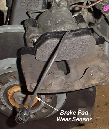
Single caliper piston and inboard brake pad with brake pad
wear sensor integrated into the pad.
When installing new pads with built in brake pad wear sensors, just hook them back up when performing the brake job and youll be on your way!
However, many aftermarket brake pad sets do not have the sensors installed. Therefore, the old sensors must be cut off the old pads, the wire insulation stripped, the wires twisted together, wrap them in electrical tape, fold them over and tie wrap the whole thing up. Then plug it into the car side harness. This maintains continuity in the circuit, which will prevent the brake pad wear sensor light from coming on.
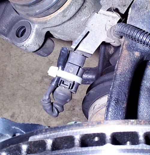
Brake sensor wiring cut off old pad, shorted out, taped up and tie wrapped in place. This will maintain circuit continuity so the brake pad warning light wont come on.
Photo courtesy of Jeff Bipes.
In the case that this was done, but the light still comes on, it needs to be troubleshot. The following outlines how to troubleshoot the bad connection. Remember, the circuit should be a short circuit. The brake pad warning light comes on when the circuit opens.
Troubleshooting the Brake Pad Warning Light
The brake pad warning light circuit is a ground path loop. When this ground path is interrupted (open circuited, like turning a light switch off), the brake pad warning light (K32 in image) comes on.
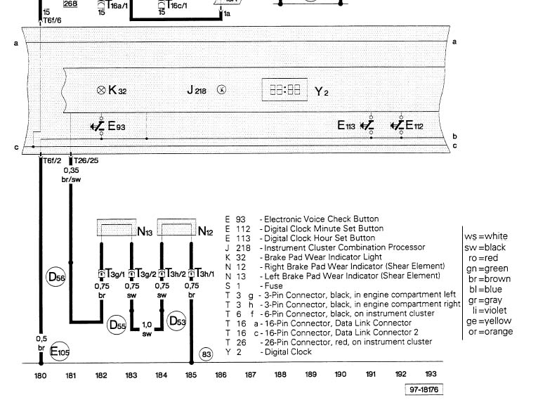
The brake pad wear circuit starts from the back of the instrument cluster (pin 25 on red 26 pin connector), through the firewall somewhere, to T3g, pin 1 (3 pin connector back left of engine compartment) to N13, which is the brake pad wear indicator, left. It then goes back to T3g, pin 2 and over to T3h, pin 2 to N12, the right brake pad wear indicator. Then back through T3h, pin 1 which is then connected to chassis ground at point 83. 83 is ground connection 1, in right front wiring harness.
Follow that path, it goes from the sensing circuit which is at 12 VDC to ground at point 83 which is chassis ground. When this circuit is interrupted, the light comes on. Easy? Yes, it really is.
The wiring is most likely all in place and in good shape. The problem most likely lies in the plug in connector at the brake pads. Do the following first:
- Unplug the connector and on the side with the shorted wires (that use to be attached to the pads) take a resistance reading across the two pins. This should be less than 1 ohm resistance. If greater than 1 ohm, remove the tape and remake the connection. Ensure it is less than 1 ohm.
- Clean the pin and socket connections on each side of the connector. This is most likely where your problem is. Use contact cleaner from Radio Shack with a small brush.
- Make up the connection, start the car with your foot on the brake, then put it in gear and check for the light (will only light up with the car in gear). If it went away, youve found your bad connection. If not, take resistance readings to ground as outlined below.

Ensure you clean the contacts of the sensor connector on both male and female side. This is most likely the problem. Follow directions above. Resistance readings across the two shown contacts should be less than 1 ohm. If not, remake connections.
So how to troubleshoot? Pretty easy. Find three pin connectors T3g and T3h in the engine compartment. I believe this connector is down at the bottom front of engine compartment, forward of the wheels on each side. The belly pan would have to be removed first.
Perform a continuity check from the brake pad side of pin 1 on T3g to the brake pad side of T3h pin 1. You disconnect these connectors, hook up a multimeter on the resistance range, and you should have 1 ohm or less for continuity.
But if your brake pad wear light is on, it will probably be an open circuit (greater than 2000 ohms, most likely infinity).
Measure the continuity across each of the brake pad wear indicators as shown in the image. One will most likely be shorted (continuity) and the other will be open circuited. Find the one that is open circuited and repair as required by shorting the brake pad wear sensor wires. You probably put on aftermarket pads that didnt have them and now the old ones need to be cut and twisted together to create the ground path.
If these circuits tested good, then take a resistance reading from the ground side of T3h pin 1 to a known ground location. You should have continuity (short circuit). If not, troubleshoot and repair wiring.
If that tests good, pull the instrument cluster and check continuity from T26 pin 25 to T3g pin 1. There should be continuity. If not, repair wiring.
Want to skip all these tests at first? Find T3g pin 1, and connect the instrument cluster side to ground with a jumper wire. Turn the car on, did the brake pad warning light go off? If so, you know the problem is down stream. You could reconnect it and do the same from T3h pin 2. If the light is still off, you know the problem is down stream of that point.
2005 Accord Hybrid Online Reference Owner’s Manual
Afterwards, keep this owner’s manual in your vehicle so you can refer to it at any time. Several warranties protect your new vehicle. Read the warranty booklet thoroughly so you understand the coverages and are aware of your rights and responsibilities. Maintaining your vehicle according to the schedules given in this manual helps to keep your driving trouble-free while it preserves your investment. When your vehicle needs maintenance, keep in mind that your dealer’s staff is specially trained in servicing the many systems unique to your vehicle. Your dealer is dedicated to your satisfaction and will be pleased to answer any questions and concerns.
Download: 2005 Honda Accord Hybrid Owners Manual Guide
Thursday, April 4, 2013
Audi A4 B5 Changing the Cabin Air Filter
Tools needed:
Ratchet and socket set
Flat and Phillips head screwdriver
Car keys
30mins of time
Park windshield wipers in the 12 oclock position.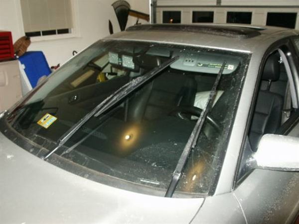
Remove the rubber strip by pulling it towards the front of the car.
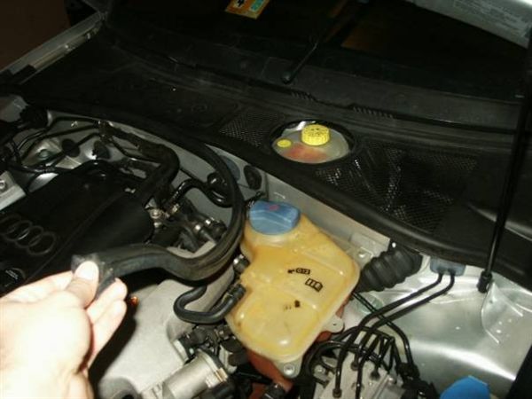
Pull the battery firewall cover out towards the front of the car.
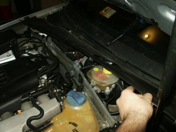
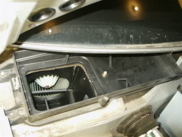
Cabin air filter is underneath the windshield plastic cover on the passenger side. Turn the screws and then use the ratchet and remove the bolt in the middle of the picture and pull the cover out towards the front of the car.
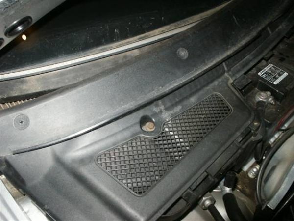
There is a drip pan that needs to be pulled out hardly but gently towards the front. Make sure that the wholes on the drip pan are clear from any debris before you put the thing back in.
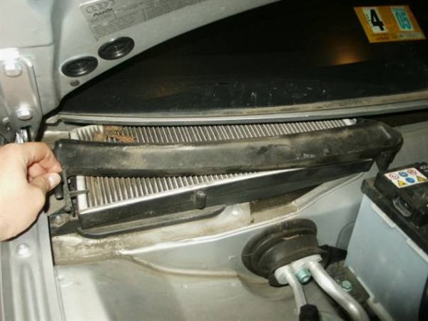
Pull the old filter out and clean the now exposed cabin filter box with a moist sponge to remove any dust that is in there.
Old filter versus new... yeah it needed replacement.
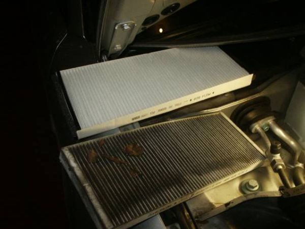
The part number on the air filter that bought was CU 3955 and was a special order at AutoZone for $19.
Put everything back together in the reverse order and you should be set.
Alfa Romeo Alfa 159 and Alfa 159 Sportwagon Owner Manual And Specifications
performance, while external dimensions of 4,660 by 1,828 by 1,417 millimetres give an imposing presence, and allow for a generous amount of interior space. The difference between the saloon and the Sportwagon lies in their luggage capacity: while the Alfa 159 is characterized by its neat, compact size, the Sportwagon is an incredibly versatile vehicle that boasts 1,235 litres of space with the rear seats folded down.Climb behind the wheel of Alfa 159 and Alfa 159 Sportwagon and get ready to enjoy maximum driving pleasure and to.giftal control of your car. Once out on the road, you will experience extraordinary stability even at high speeds, outstanding roadholding and agile handling. This is made possible by the high torsional rigidity of the body, and the suspension geometry. In particular, the quadrilateral front suspension guarantees predictable, precise steering responses. The multi-link rear suspension, meanwhile, ensures optimum road contact at all times. The end result is a sensation of complete control which is unrivalled by any other car in the same class as the Alfa 159 and Alfa 159 Sportwagon.
: Alfa Romeo Alfa 159 and Alfa 159 Sportwagon Owner Manual And Specifications
Wednesday, April 3, 2013
CD Changer Removal and Phatnoise Install
The CD changer is inside the drivers side rear drivers side panel.

In order to remove the unit there is some work involved but it should take more than 30mins.
Remove the back plastic cover, its held to the car with like 10 phillips screws. pull it out.

Now fold the carpet back

Also remove the black pastic rubber grommet that is just slightly above the black plastic piece that you have just removed. This grommet is covering up a screw and is also used to hold the panel in place. After you have removed it, pull semi hard onto the panel and peel it into the trunk area

The panel is clipped to the inside with these 2 clips and the bolt with the rubber grommet.

You should now have a clear view of the CD Changer and its braket that holds the sucker in there.
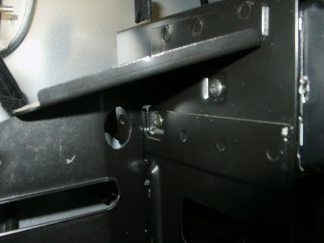
For the CD Changer installation or removal you will have to take the bracket out due to those 2 screws that are inaccessible on the other side. Photo shows the rear of the bracket.
There are 2 bolts just underneath the taillight bulbs, 2 on the bottom and one that is just underneath the amplifier as shown here:

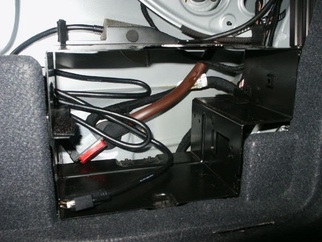
Be care full after you have the bracket loose because of the radio cables that are mounted underneath:

The connectors that are used in the car:


Remove the 2 bolts per side that are holding the CD Changer unit in the bracket. The unit will now slide out. Well you need to disconnect the Round cable first.
Side by side comparisms of the cd changer and the Pbox:


You could now reinstall the bracket with the phatbox permanently mounted with the screws supplied and have it fixed or do my modifications so you can switch in between phatbox or cd changer as you want.

Also for those CD Changer owners complaining about skipping when driving over bumps. Buy yourself some rubber patch for 1$ at the local hardware store and cut some small sections as shock absorbers and install them in between the bracket and frame of the car. I wanted to always try that but it should absorb some of the bumps that you encounter daily.

Whatever you want to do is up to you, but install the bracket back into the car and have the phatbox in it. Put the interior back together and program the sucker.
Here is what i did: Use some velcro tape and attach it to the phatbox and the bracket.

The phatbox is slightly thinner than the CD Changer so you can "fly" it into the bracket and then just push it down having the velcro nipples make contact and hold the thing in there.
I got my phatbox from one of the local AWMA Mod Crew Members and he made a CUSTOM setup when he had his installed in his S4:


Now thats what i call custom fit! We swapped those as well. For reference the cartridge doesnt stick out that far its for the picture only. i actually would have have flip the panel right now to remove the cartridge.
Depending on your car radio and setup and stuff you will have to buy the AUDI CABLE seperatly and you will need to configure the unit to run with certain cars and radios.
If you have a Symphony radio hit the CDC button, then "6" and scroll until 22 appear and the chick says Unit Q or something like that. Refer to one of the 7 Pdfs that accompany the unit for reference.
Hope this helps!
The newest music manager software is here
BTW They have different languages available and the german one (native to me) sounds very sexy...
Audi A8 Replacing Rear Pads and Rotors
Replacement of rear rotors and pads is an easy task, even if youve never done it before. Consider replacing both if your rotors have 50,000 miles or more on them. This will prevent you from having to do the job again anytime soon. Plus, you dont have to get the rotors turned, which can be a real hassle if it is not done correctly or you dont have two vehicles.
If the rear brake pads are worn down, the fronts are probably not far behind. Check them while doing the rears. The rears DO NOT have wear sensors. When the brake pad backing plate comes in contact with the rotor and metal to metal contact is heard, you will know its time to do the rears!
All A8s and S8s had the same rear brakes. This procedure is applicable to all models.
Special Tools Required
- 8 mm Allen wrench to fit to a 3/8" rachet drive (only needed if replacing rotors)
- Large C-clamp to push the piston back in the caliper
- Channel locks or Harbor Freight tool to push the piston back in the caliper
- Metric sockets
- 15 mm open ended wrench
- Caliper lube
- Brake cleaner and rags
The following picture is from the Bently manual. It identifies the major brake components.
Figure 1
Procedure
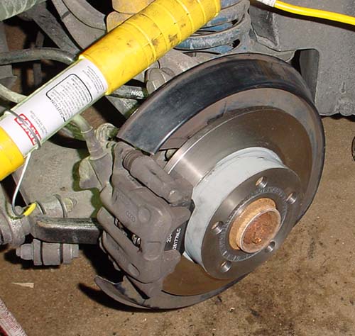
Take lug nut caps off and loosen lug nuts. Jack the car up and put the rear end up on jack stands. Raising the entire rear end makes the job much simpler and safer. Remove wheel.
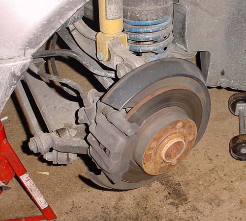
A8 Rear Brake Assembly.
Using a 15 mm open ended wrench, hold the nut shown in the picture below (part of Item 3, Figure 1). Using a 13 mm socket or wrench, loosen the bolt just inboard of it (Figure 1, item 1). Repeat for second bolt assembly.

Use a 15 mm open end wrench to hold the nut from spinning while loosening the bolt just inboard of it. The top bolt has already been unscrewed.
Remove caliper assembly by lifting it up and off. Have wire ready to tie it up or rest it on the suspension arm. Do not allow it to hang from the brake line!
If removing rotors to replace them or to have them turned, remove the two carrier retaining bolts (Figure 1, Item 4) using an 8mm allen head socket. Remove carrier.
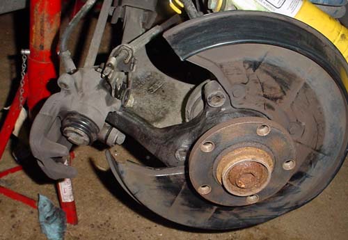
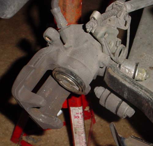
Rear caliper and rotor removed. Piston has not been pushed back in cylinder yet.
There are several ways to get the piston back in the caliper. It must be screwed in using a clockwise motion with pressure on the piston. This can be accomplished by using a large C-clamp and channel lock pliers or by buying the caliper tool set for disc brakes from Harbor Freight Tool Company. This tool not only provides the pushing force, but also screws the piston back in at the same time.
Caliper tool set from Harbor Freight Tools.
Part number 40732. This makes the job really easy!
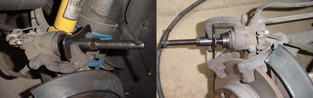
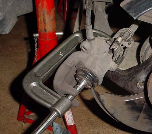
Using a large C-clamp, place slight pressure on the piston.
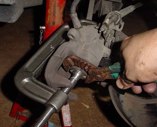
Turn the piston in about 1/2 turn, then readjust the C-clamp to apply pressure again. Each time the piston is screwed in, the C-clamp must be tightened. Its a real pain to do. With the Harbor Freight tool, its a breeze. If you plan on doing the rears more than once, it would be a good investment. If using the C-clamp method, make sure you have at least a 6" C-clamp.
Piston screwed all the way into cylinder. Ensure you screw it all the way in otherwise there will not be enough clearance to get the caliper over the new pads.
Clean all brake components with brake cleaner and rags. Pull the small boot off the caliper assembly (Figure 1, Item 6). Lube the assembly with caliper lube. This allows the brake caliper to float better due to braking forces and brake pad wear.
Installation of New Components
Prior to performing installation, take a break and wash your hands! Remove all grease from them. If you bought new rotors, clean the rotor off of all protective material and paint. Wash your hands again and ensure they are clean before reassembling.
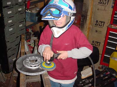
Evan Waterloo, using his Dads DA sander to clean and
scuff the surface of the rotors (front rotor shown).
Prior to installing the new rotor, take some grease or caliper lube and put it on the hub where the rotor comes in contact. This will prevent the rotor from rusting to the hub assembly.
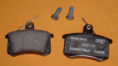
OEM pads. The OEM pads come with new bolts.
Install new rotor.
Install carrier bracket using 8 mm allen head bolts. If using OEM pads, remove backing sticker and place both pads in carrier assembly.
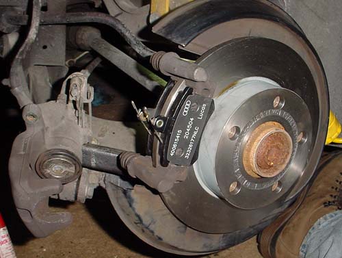
Pads placed in carrier assembly prior to installing caliper.
Install the caliper on the carrier assembly. When doing this, ensure both pad springs are properly seated and the guide pins are pushed in and out of the way. Start the bolt (Figure 1, Item 1) on the top first (dont tighten it, just get a few turns on it) and then compress the springs by pushing down on the caliper and starting the bottom bolt.
Tighten both bolts down, torque to 35 Nm. Always replace bolts with new, OEM pads come with new bolts.
Completed rear brake job. Cleaning all the components
prior to installation is an important step!
Audi A3 DIY Adding Power to the Armrest
Remove the armrest. Single 14mm bolt.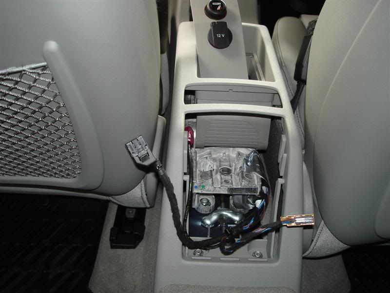
Drill a hole, and add a gromet.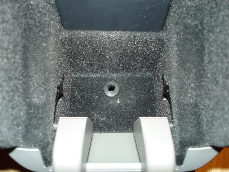
Remove the endcaps to the armrest, and run the wiring through the armrest. The grommet I had was too small for the connector. I had to cut the cable, run the wiring through the grommet, and then resolder it back together. (Forgot to take a picture, but you can see the existing wiring.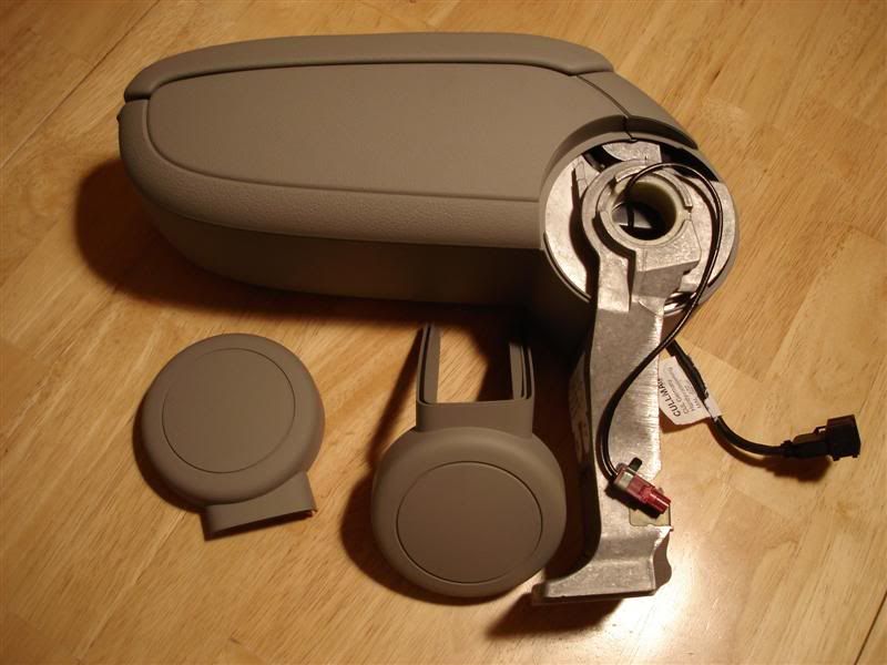
For a car adapter, I purchased a universal adapter from Radioshack. You can use it for different phones, pdas, mp3 players, etc. You only need to buy a different connector (~$2 per connector).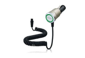
Next is to get power to the car adapter. I decided to get power from the backside of the cigarrette lighter. Probably committed a cardinal sin by cutting and soldering in the wiring. IMO, its much more reliable then a wire tap (provided you know how to solder). In case you cant tell, I added the white wires. Dont forget to pull the fuse, and measure the voltage before you do any cutting, or soldering.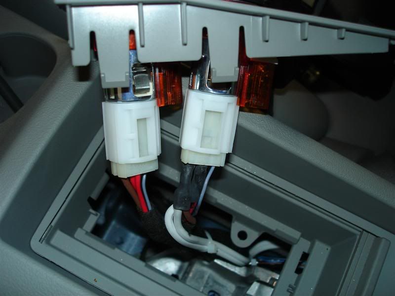
Next step is to wire in a female portion of a car adapter (also from Radio Shack) to the cable just connected to the cigarrette lighter.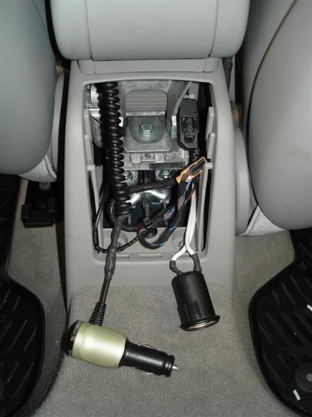
Connect the two, and their you have it. Power in the armrest. Still need to get a final picture of my phone in the armrest. Too bad with the Razr, it barely fits since the power comes off the side.